
NewsDetails
What are the common specifications for manholes? How should the installation location be selected?
author:Kairuifeng time:2026-09-29 22:19:22 Click:82
Question: What are the common specifications for manholes? How to choose the installation location?
A manhole is an important safety accessory for pressure vessels, storage tanks, reactors, and other equipment, providing access for personnel to enter the equipment for inspection, cleaning, and maintenance.
I. Common Specifications of Manholes
1. Nominal Diameter: DN400, DN450, DN500, DN600. Among these, DN500 and DN600 are the most commonly used, while DN400 and DN450 are suitable for small equipment or space-constrained applications. Selection principle: It should meet the requirements for personnel to enter and exit with tools, generally not less than DN450, with DN500 or larger recommended.
2. Nominal Pressure: Atmospheric pressure, PN0.6, PN1.0, PN1.6, PN2.5, PN4.0. The nominal pressure of the manhole shall not be lower than the design pressure of the equipment, and temperature correction shall be considered.
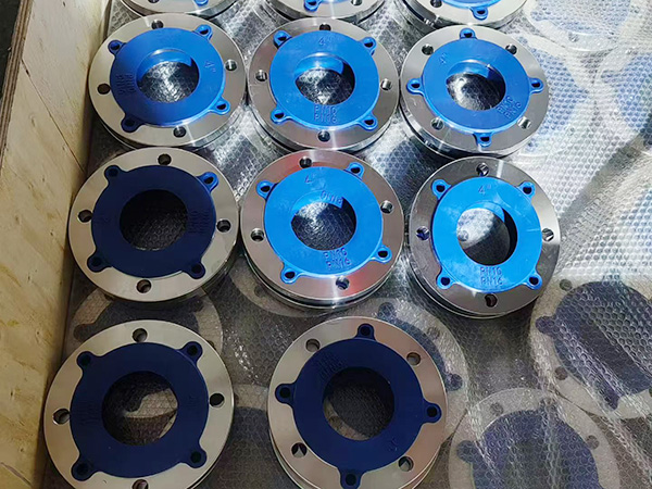
3. Structural Forms: The rotary cover manhole is the most commonly used, with the cover rotating around a hinge pin for convenient opening and closing; the vertical lift cover manhole is suitable for the top of equipment; the horizontal lift cover manhole is suitable for large-diameter manholes on the side walls of equipment; the quick-opening manhole opens rapidly and is suitable for applications requiring frequent access; the atmospheric manhole is suitable for atmospheric or slightly positive pressure storage tanks; the core-equipped manhole features an anti-vortex baffle and is suitable for the side walls of storage tanks.
4. Material: Carbon steel (Q235, 20#, Q245R, Q345R), stainless steel (304, 304L, 316, 316L), alloy steel (15CrMoR, 12Cr1MoVR). Gaskets are selected based on the medium and temperature, including asbestos rubber gaskets, flexible graphite gaskets, metal wound gaskets, and PTFE gaskets.
II. Principles for Selecting the Location of Manholes
1. Facilitate personnel access and egress: The center of the side-wall manhole should generally be located 750 to 1500 mm above the ground or operating platform, with an optimal height of 1000 to 1200 mm, and at least 1 meter of clear operating space in front. The top manhole should be installed at a convenient climbing position on the top of the equipment, equipped with a ladder, operating platform, and safety guardrails.
2. Facilitates inspection and maintenance: It should be located near components that require frequent inspection (such as agitators, heat exchange tubes, and internal components); large equipment should be equipped with multiple manholes arranged at different locations; it should avoid internal obstacles to ensure sufficient working space for personnel after entry.
3. Meeting Process Requirements: The manhole on the side wall of a liquid storage tank should be installed above the liquid level to prevent the medium from flowing out when opened; the manhole on a reactor should be installed on the upper part or top, avoiding the rotation range of the agitator; the manhole on equipment containing solid particles or viscous media should be installed at a location convenient for cleaning deposits (bottom or conical bottom).
4. Ensure structural safety: Openings should avoid areas of stress concentration (weld joints between the shell and heads, and areas near supports); reinforcement calculations should be performed for openings, and reinforcement rings should be installed if necessary; the distance between adjacent manholes should not be too small; non-destructive testing should be performed on the weld joints between the manhole flanges and the shell.
5. Consider Safety Protection: Avoid facing operational aisles or areas frequently traversed by personnel; install anti-scald protection or warning signs for high-temperature equipment; position manholes of equipment containing toxic, flammable, or explosive media in well-ventilated locations; and install safety lighting and communication facilities nearby.
III. Recommendations for Manhole Layout on Different Devices
Vertical Storage Tank: One top manhole (DN500 or DN600) is installed at the top; one to two manholes (DN500) are installed on the lower part of the side wall, located 750 to 1000 mm from the tank bottom; multiple manholes can be installed at different heights for large storage tanks (diameter not less than 5 m).
Horizontal Storage Tank: One manhole is provided on the top of the shell, with the center of the manhole located at a distance of no less than 1/4 of the shell diameter from the end of the shell.
Reactor: One manhole (DN450 or DN500) is installed on the upper part of the reactor body, arranged to be offset from the charging port and the observation port; a quick-opening manhole can be used for high-pressure reactors.
Shell-and-tube heat exchanger: A manhole is provided at the tube box end; a shell-side manhole may be installed on the shell side of large-diameter heat exchangers.
Column: One manhole shall be provided every 10 to 15 meters along the column height, with a minimum of two manholes; the manholes shall be located between the trays, approximately 600 to 800 mm above the tray; and arranged alternately on both sides of the column body.
IV. Determination of the Number of Manholes
At least one for small equipment (volume not exceeding 1 cubic meter); one to two for medium-sized equipment (1 to 10 cubic meters); two or more for large equipment (exceeding 10 cubic meters); one per 10 to 15 meters of tower height for towers, with a minimum of two; an appropriate increase for equipment containing toxic, flammable, or explosive media.
V. Installation Precautions
1. Before installation, inspect the flange sealing surface for radial scratches or dents, and ensure the gasket is in good condition;
2. Ensure the welding quality of the manhole flange to the shell, and perform non-destructive testing after welding;
3. Bolts are tightened symmetrically and evenly, with the tightening torque conforming to the specifications;
4. After installation, conduct a hydrostatic pressure test and an airtightness test to confirm there are no leaks;
5. Operate slowly when opening. First, loosen the diagonal bolts to release the pressure, and only fully open after confirming that there is no pressure.
6. After closing, confirm that all bolts are tightened and the gasket is correctly positioned.
Cangzhou Kairuifeng Pipeline Equipment Co., Ltd. specializes in the production of manholes for pressure vessels in various specifications and types. Customization is available. Feel free to contact us for inquiries and purchases.
 Contact us
—— Contact:Manager
—— Tel:+86 15720204999
—— Email:zeleiliu97@gmail.com
—— Url:https://www.krfpipe.com
—— Address:No. 108 Longhai West Road, Yanshan Town, Yanshan County